

This note clarifies a recent IT issue identified in the HERA – Composite Slab & Beam Design Software, where an extraneous random variable appears in the calculation of longitudinal shear resistance for composite steel-concrete beams.
For the design of steel-concrete composite beams, the provisions outlined in Clause 3.8 of AS/NZS 2327 and Clause 13.4.10 of NZS 3404 design standards are applicable. According to Clause 3.8.1 of AS/NZS 2327:
“The design longitudinal shear stress for any potential surface of longitudinal shear failure within the slab, 
Based on these guidelines, the decision was made to adopt the design procedure outlined in Eurocode 4 (EN 1994-1-1:2004), which aligns with the aforementioned explanation of the AS/NZS 2327 design standard.
As specified in EN 1994-1-1:2004, the beam length is divided into distinct zones, each with varying arrangements of shear connectors. The force per unit length transferred by the shear connectors is calculated for each zone, and the maximum value among these is utilised in the design calculations. Therefore, based on this design standard:
The force per unit length that can be transferred by the shear connectors is taken as:

where


where


In the software, the design longitudinal force is therefore modified to reflect the highest utilisation for any element within the cross-section, and for any over-provision of connectors (beyond that required for 100% shear connection). The engineering basis for this is explained in SCI Advisory Desk Note AD 439. This effect is taken into account using maximum unity factor for bending (
For an edge beam, the applied longitudinal shear force per unit length is taken as:

where


For internal beams, the applied longitudinal shear force per unit length is taken as:

In the software, 
To provide further clarification, the following calculations are presented for an internal beam with the length of 10 mm designed using both the software and manual hand calculations:
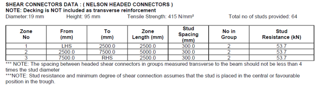
The beam is divided into three zones, and the parameters for all zones are as follows, since the shear studs are uniformly distributed along the beam:


Therefore, for all three zones:

The degree of shear connectors in this example is 68%; therefore, the number of shear connectors required for full shear connection is:

Subsequently, for an internal beam:

Based on the results obtained from the software:
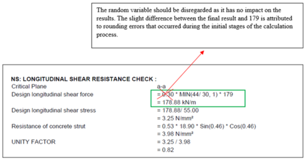
As a result, the random variable is included in the calculation sequence but remains mathematically neutral, exerting no influence on the computed shear resistance values. Testing has confirmed that this variable, attributed to an IT issue, does not affect the results, ensuring the tool’s accuracy remains intact. Users can therefore disregard the presence of this random variable and confidently use the software’s output.
References:
[1] Standards Australia/Standards New Zealand, Composite structures – Composite steel-concrete construction in buildings, AS/NZS 2327:2017, Sydney, Australia; Wellington, New Zealand: Standards Australia/Standards New Zealand, 2017.
[2] Standards New Zealand, Steel structures standard, NZS 3404:1997, Wellington, New Zealand: Standards New Zealand, 1997.
[3] European Committee for Standardization, Eurocode 4: Design of composite steel and concrete structures – Part 1-1: General rules and rules for buildings, EN 1994-1-1:2004, Brussels, Belgium: CEN, 2004.
[4] Steel Construction Institute, Advisory Desk Note AD 439: Shear connector resistance in composite construction, Ascot, UK: Steel Construction Institute, 2017.